This is the notes of Digital Communication, corresponding to Chapter 2 of Digital Communication by Proakis mainly about the bandpass and lowpass signal representation.
BANDPASS AND LOWPASS SIGNAL REPRESENTATION
Where the Imagenarty Part Comes From?
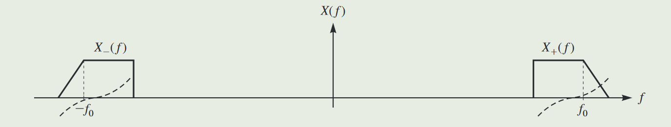
Assume that we have a real-valued signal x(t), and the spectrum of x(t) is X(f). The spectrum of x(t) is Hermitian symmetric:
X(f)=X∗(−f)
The summetric property of the spectrum can be shown as:
So we can reconstruct the real-valued signal x(t) as we get the assess to the X+(f), which is the positive part of the spectrum of x(t). The inverse Fourier transform of X+(f) is x+(t):
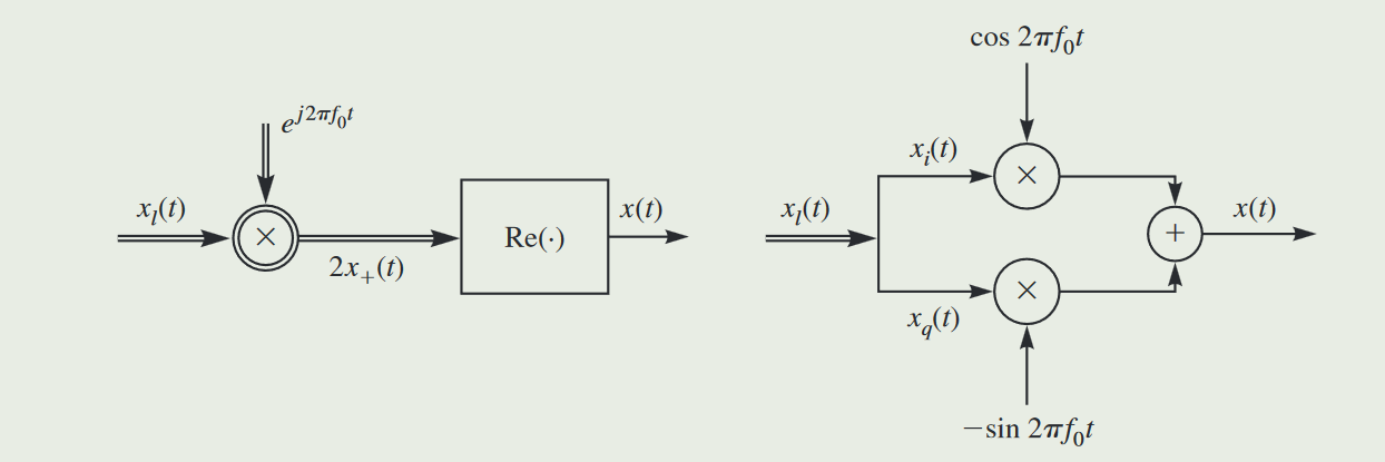
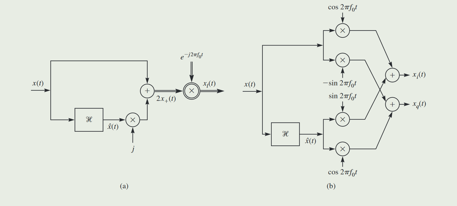
The real and imaginary parts of xl(t) are called the in-phase component and the quadrature component of x(t), respectively, and are denoted by xi(t) and xq(t). Both xi(t) andxq(t) are real-valued lowpass signals, and we have:
According to the above equations, we can get the structure of the modulator and demodulator of the bandpass signal x(t):
Lowpass Equivalent of a Bandpass System
In the preceding section where we talk about the lowpass equivalent of a bandpass signal, we can also get the lowpass equivalent of a bandpass system, whose impusle response is h(t) with a lowpass equivalent hl(t):
The input-output relation between the lowpass equivalents is very similar to the relation between the bandpass signals, the only difference being that for the lowpass equivalents a factor of 21 is introduced.